|
This is a step-by-step of how I modified my LGB switches to utilize Tenmille's 16mm point levers. You will need the following:
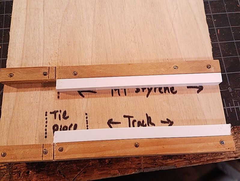
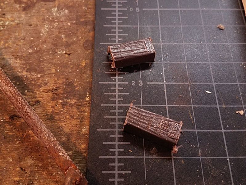
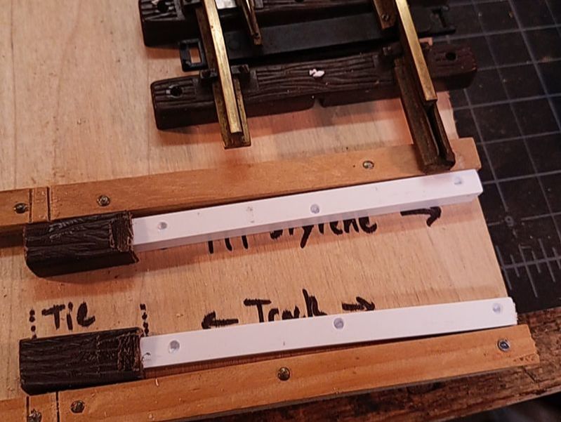
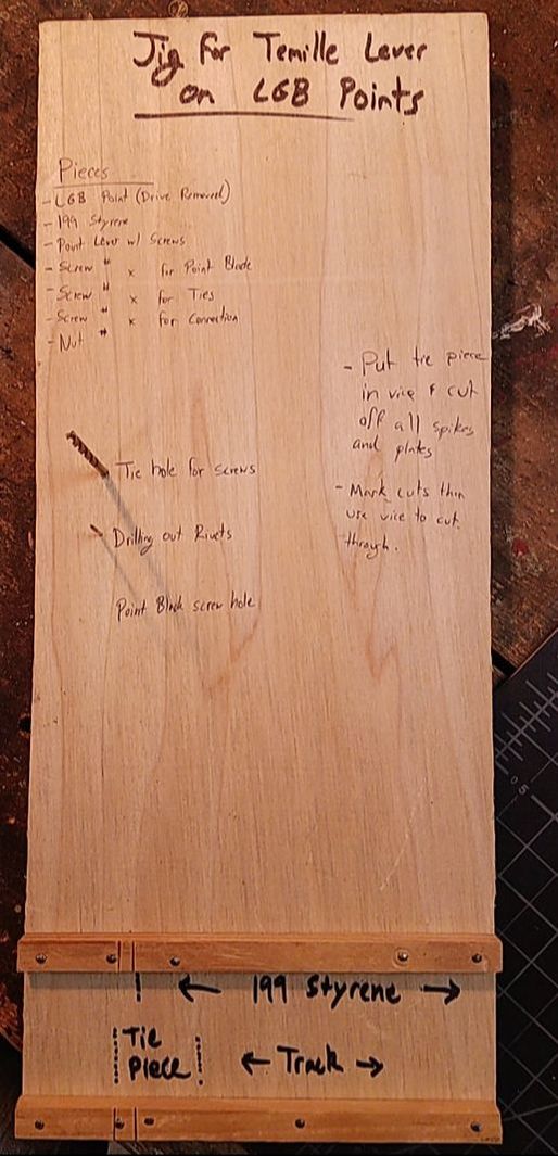 I created a jig after testing the effectiveness of adding a lever to one of my order LGB switches. It includes all the necessary information I need to build a switch. It also holds the switch in place when I'm drilling. You can see in this photo I had not yet written all the information down yet (and still, writing this post, it is not written on the board). Note the bottom of the jig, where I have all measurements marked out to make consistency easy. Step 1: Prep your PiecesMuch like in my baking career, before I begin my project, I mise en place. This is French for everything in it's place. Basically, it means that I prep all necessary parts and make sure I have everything before I start. In this hobby, it's not such an issue if you're missing a screw, but, in baking, if you're missing an ingredient and you're half way through mixing a cake, it's much worse! You can see in the below photos that I have cut my two styrene pieces to the proper lengths and I have also lightly sanded the ends to get rid of any filings. Then, I cut apart an only LGB flex tie section and cut off the tie plates. Then I cut the tie apart just at the end of the slot. I am then able to cut the tie into appropriate-length pieces. I feel most modelers won't like how close I am keeping my levers to the rails, as it is not prototypical. So, feel free to modify that detail as you see fit.
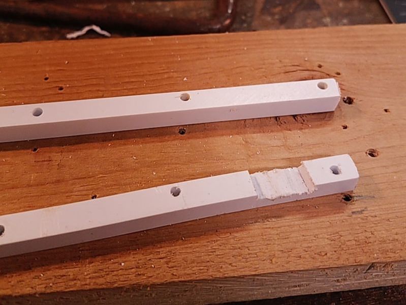
Next I lay the styrene into the tie strips of the switch and drill screw holes (sides) into the pieces, as well as a hole for the drag plate to fit into (center holes). After that I cut a notch in the bottom piece of styrene so it fits around the notch in the bottom tie (see center photo - notch is above the rail joiner). I have not yet drilled holes for the tie extensions.
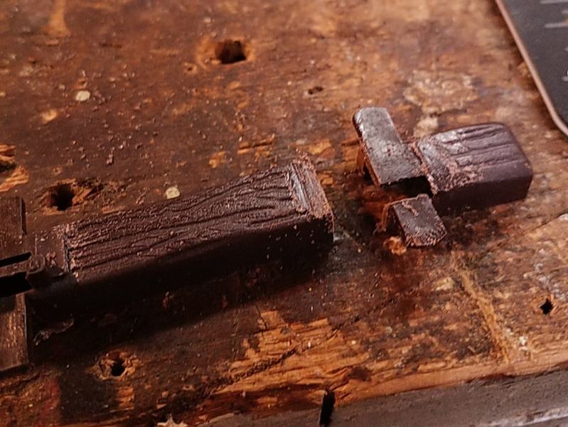
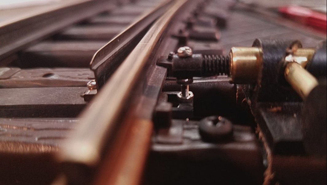
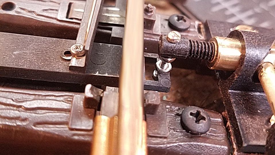
Part 2: Begin Building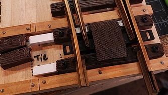 Next, screw the ties together with their new styrene supports. Then make sure that the drag plate fits into it's holes in the styrene. You may need to widen the holes slightly. I found that wiggling the drill bit around a bit worked well. Personally, I want it to fit snug, but if the hole is too big, it will still hold onto the tie itself, so no worries. Part 3: The LeverYou may know that 16mm point levers will not have enough movement to get the LGB point blades all the way from one side to the other. The missing distance is small, but it is enough to derail a train. Thus, it is necessary to detach one of the point blades and move it over about 2-3 mm on the throwbar. This is a slightly more complicated process. To simplify, I'm going to use bullets:
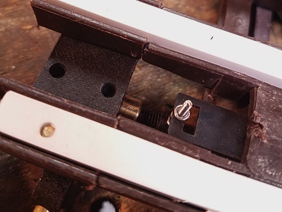
Part 4: Replacing the RivetIn order to get both point blades to touch the stock rails properly, you need to move one of them a few millimeters. Here's how I did it.
I did find that I still have a bit too much movement in my points. I am considering replacing the throwbar all together, which would give me more control over the 'give' that the connections have. However, I'm not sure I'd trust the styrene to hold up as well. Please feel free to contact me with comments, ideas, of questions! Update: May 8th, 2018After a bit more trial-and-error I've found that there is enough space in the end of the throw bar (between the slot and the end of the piece) to drill a hole for the 0-80 screw connecting the bar to the lever. This is what I am doing with all my pieces now, as it allows for more control over the movement of the throw bar and, thus, the points themselves. When I moved the screw from the slot in the throw bar to the new hole I drilled the unit went from 90% proper movement to 100% movement.
0 Comments
Leave a Reply. |
Hello!My name is John. This is my website dedicated to all things model railroading! I hope you enjoy! Archives
March 2020
Categories
All
This site was last updated
at date of top Project post or more recently. |

 RSS Feed
